Lessons · Lesson M2 · Mechanics and 3D · 25 min
3D printing for your projects
Go from a model to a printed box that fits: measuring, clearance, walls, screw holes, battery bays, overhangs and PLA settings. About 25 minutes, with a clearance slider.
From a model to a box
A 3D-printed box is a model on a screen turned into plastic, layer after layer. The path is always the same:
- Measure the parts that will go inside (screen 2).
- Model the box around them, with some room to spare.
- Slice: a program called a slicer cuts the model into layers and writes the instructions for your printer.
- Print a small test piece first (screen 2).
- Print the real thing, test it, adjust, print again if needed.
Take mission 01’s box as a guide. It has a base that holds the circuit board and the battery bay, a lid with the cut-outs for the switches, and a few screws to hold it together. An exploded view shows every part pulled apart, in the order they go in.
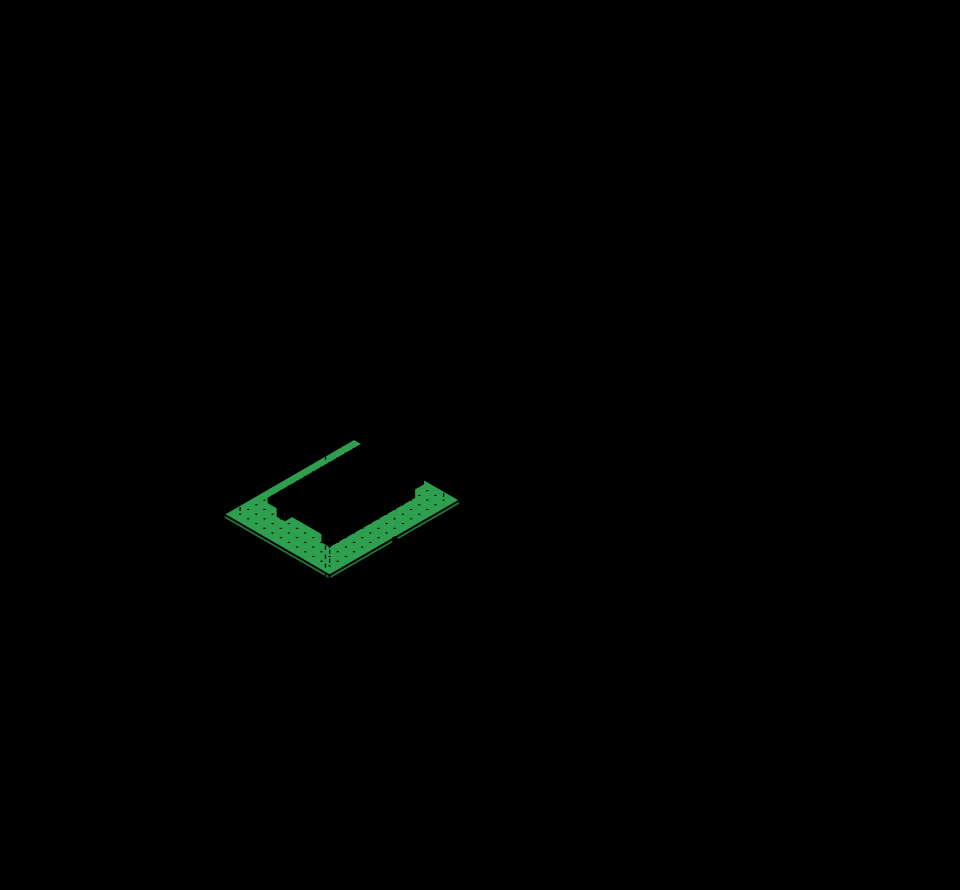
No printer? Every Tinker Mission project also has a path without one: a cardboard box or a ready-made case works, and what you learn below about measuring and leaving room still applies.
Measure, add clearance, print a test piece
Measure your real parts with calipers. Do not trust a number from a drawing or a shop page: measure the actual board, the actual battery holder, the actual switch. Write the numbers down.
Add clearance. A printed part never comes out exactly the size of the model, and your parts are never exactly the size you measured. If you design a pocket with exactly the measured size, the part will probably not go in. So you add a little room, called clearance, on each side.
Our rule of thumb (not a standard): start at about 0.3 mm per side. Smaller values risk a part that does not go in. Larger ones give a looser fit that may rattle. Printers differ, so this is only a starting point.
Use the slider below to feel the difference.
Our rule of thumb, not a standard. Printers differ.
Good starting range: 0.3 mm is our usual start.
Then print a test piece.
This is the starting state: the controls need JavaScript.
Print a small test piece first. Model only the interesting bit: a short length of the pocket, one screw hole, one slot for the switch. It prints quickly and uses little plastic. Put your real part in it, and measure the printed pocket with the calipers. If it is too tight, add 0.1 mm per side. If it is loose, remove 0.1 mm per side. Only then print the full box.
Walls, screw holes and battery bays
Walls. The number of outlines (“perimeters”) that form a wall sets most of a print’s strength, more than the infill, and Prusa’s own profiles use at least two [3]. For a box with screws, our rule: at least three lines of plastic across (about 1.2 mm, which slices to three lines with a 0.4 mm nozzle on most settings), and a bit more near screws (our own boxes use 2 mm walls). Your slicer shows how many lines a wall gets: look at its preview.
Screw holes. The same idea as clearance applies:
- Where a screw must pass through a part, make the hole slightly bigger than the screw, with a clearance like on screen 2, so it slides easily. For an M3 screw (3.0 mm), what we use in our boxes is a hole of about 3.4 mm.
- Where a screw must bite into plastic, make the hole slightly smaller than the screw. For an M3 screw, what we use in our boxes is about 2.6 mm; how small really depends on your printer, so test with a small piece. Do not tighten hard: plastic can strip or split.
- Our kits mostly use M3 screws (sometimes M2.5). Measure the one you have with the calipers.
- For a circuit board, look for its mounting holes: a proto board such as Adafruit’s has two, to attach it to a project box [1]. Raise it on posts so the solder joints underneath do not touch the base.
Battery bays.
- Measure the holder you will actually use (for example a 4 × AA holder with a switch), not the cells alone.
- Leave room for the wires, and for fingers: changing the batteries should only take a screwdriver to open the lid, with nothing to unwire and no forcing.
- Put the power switch where you can reach it from outside. Switch the pack off before you plug in USB.
- Do not mix old and new cells, or different types, in the same holder. Write down the date you put them in.
Overhangs and supports
A printer builds a part one layer at a time, and every layer has to rest on the layer below. Anything that would start in empty air needs a support structure underneath [2]. A vertical wall is easy, a wall leaning outward gets harder, and a flat “ceiling” over empty space has nothing to rest on.
What the guides say, and what we do:
- Orient the part, or split it, to reduce overhangs and supports [2]. In practice a box prints open side up, base flat on the plate, and a lid upside down, flat face on the plate (our choice for these shapes).
- Keep slopes steep. When automatic supports are on, Bambu Studio’s default threshold is 30°: it adds supports where a surface slopes less than 30° from horizontal, and calls that a safe angle to print without support for most materials [5]. In our experience the underside gets rougher near that limit, so we do not treat it as a comfort zone. We design with a larger margin, and use 45° or steeper (a 45° bevel, our choice), which is kinder than a flat ceiling.
- Short bridges can print without support because both ends are held; the longer the span, the less reliable [5]. As a rule of thumb (ours), keep unsupported flat spans under about 10 mm, and expect a slightly sagging underside.
- Supports are scaffolds the slicer adds under overhangs. They are often easy to pull off by hand, with pliers for hard spots. Pieces can be sharp and fly off, so wear safety glasses, as Prusa suggests [2]. If you use cutters or a knife, cut away from your face and fingers, and younger makers ask an adult. Design to need as few as possible.
- Stay safe around the printer. The nozzle is around 210 °C and the bed around 60 °C: do not touch them while printing or just after, and let them cool before removing a part. For a jam, follow your printer’s guide, and do not touch the hot nozzle with your fingers. Keep hair, sleeves and cables away from moving parts. Print in a ventilated room and never leave a running printer unattended. Remove parts by flexing the plate if it is flexible; if you use a scraper, push it away from your hand. Younger makers: work with an adult nearby.

Print settings for PLA, and our files
PLA is a common, easy plastic for first projects, and our parts are designed for it.
- Start from your slicer’s PLA preset for your printer. Do not type temperatures from memory. For reference, Prusa recommends about 210 to 215 °C for the nozzle and 60 °C for the bed on its own printers [4]; other machines and spools differ, so follow your preset and the label on the spool.
- Layer height: keep the preset’s default for a first try. Finer layers look nicer but take longer, and Prusa finds going below 0.10 mm brings little improvement [3]. Keep it under 80% of the nozzle diameter, so at most about 0.32 mm with a 0.4 mm nozzle [3].
- Watch the first layer. Prusa’s profiles use 0.20 mm for it, to help adhesion [3]. If it does not stick, stop and fix that first.
- Know PLA’s limits. It is easy to print and good for prototypes, but it softens above about 60 °C, degrades in sunlight and is brittle on impact, so it is not for outdoor use or hot places [4]. Do not leave a box in a hot car.
- Label your part with the clearance you used, so that next time you do not have to guess. Keep small text and thin details at least about 0.6 to 0.8 mm wide (what we use in our boxes), and prefer text sunk into the part (debossed) to raised text, which can snap off or make tiny overhangs on a side wall; anything finer may not print.
Our files. The 3D files we publish (STL, 3MF, OpenSCAD sources) are shared under the licence CC BY-NC 4.0: you may use, copy and adapt them with credit to “Tinker Mission”, but not for commercial use. If you change a file to fit your own parts, that is welcome.
Try it, and troubleshooting
Try it: a 20-minute fit test.
- Measure the width, length and thickness of one of your parts with the calipers. Write them down.
- In your model (or in the file you downloaded), make a small open pocket of those sizes plus 0.3 mm on each side, with walls about 1.2 mm thick (three lines on most settings with a 0.4 mm nozzle: check the slicer preview).
- Add one screw hole for the screw you will use.
- Slice with your PLA preset and print it.
- Try your part in it, then the screw. Write down what happened.
- Adjust by 0.1 mm if needed, and print again.
If it goes wrong
| Problem | What to try |
|---|---|
| The part does not go in | Add 0.1 mm of clearance per side, and check that the first layer is not flared at the bottom |
| The part rattles | Remove 0.1 mm per side |
| A screw splits the plastic | Make the hole a little bigger, or the wall around it thicker |
| A wall cracks | Make walls thicker, especially around posts |
| A ceiling or overhang droops | Re-orient the part, add a chamfer, or turn on supports |
| The first layer lifts | Stop, clean the plate, and level or recalibrate as your printer’s guide says, then restart |
| A battery cannot be reached | Redesign the bay, because the box should never need to be forced open |
Check yourself
Three short questions. Nothing is saved, take your time.
Your calipers say a circuit board is 51.0 mm wide. You want 0.3 mm of clearance on each side. How wide do you make the pocket in the model?
- 51.0 mm
- 51.6 mm
- 50.4 mm
Show the answer
51.6 mm. Clearance is added on both sides: 51.0 + 0.3 + 0.3 = 51.6 mm. This is our rule of thumb, and your test piece has the last word.
Why do we print a small test piece before the whole box?
- To find out in a few minutes whether the fit is right, before spending hours and plastic on the full box
- Because the printer needs a warm-up
- To check the licence of the file
Show the answer
To find out in a few minutes whether the fit is right, before spending hours and plastic on the full box. A small piece with just the pocket, hole or slot you care about prints quickly. If it is too tight or too loose, you change one number in the model and try again.
You want to print a box lid with a wide flat ceiling hanging in mid-air. What is the best idea?
- Nothing to change, plastic holds itself up
- Turn the part so that the wide flat face lies on the build plate, or add supports
- Make every wall paper-thin
Show the answer
Turn the part so that the wide flat face lies on the build plate, or add supports. A printer builds in layers, and each layer needs something under it. Wide unsupported spans and nearly flat overhangs sag, so we orient the part to avoid them, or add supports and clean them off afterwards.
In short
- Measure real parts with calipers, then add about 0.3 mm of clearance per side (our rule of thumb).
- Print a small test piece first, adjust by 0.1 mm, then print the box.
- Walls of three lines or more, screw holes sized for pass-through or bite, battery bays with room for fingers and an outside switch.
- Orient parts to avoid overhangs; use supports only when needed.
- Start from the PLA preset. Our 3D files are CC BY-NC 4.0.
Sources
Show the 5 sources
- Adafruit, “Adafruit Perma-Proto Quarter-sized Breadboard PCB” (a proto board with two mounting holes so you can attach it to a project box) — https://www.adafruit.com/product/1608
- Prusa Research, “Support material” (each layer must be supported by the one beneath; change orientation or split the model to reduce overhangs; removal by hand or pliers; pieces can be sharp and fly off, wear protective glasses) — https://help.prusa3d.com/article/support-material_1698
- Prusa Research, “Layers and perimeters” (perimeters set most of the strength, Prusa profiles use at least two; layer height below 80% of the nozzle diameter, about 0.32 mm for a 0.4 mm nozzle; little gain below 0.10 mm; 0.20 mm first layer) — https://help.prusa3d.com/article/layers-and-perimeters_1748
- Prusa Research, “PLA” (easy to print, for beginners and prototypes; recommended nozzle 215 °C first layer then 210 °C, bed 60 °C; softens above 60 °C, degrades under UV, brittle) — https://help.prusa3d.com/article/pla_2062
- Bambu Lab Wiki, “Support” (supports needed because of sagging at large overhangs; threshold angle default 30° to the horizon, safe for most materials; short bridges print well without support) — https://wiki.bambulab.com/en/software/bambu-studio/support