Lessons · Lesson A4 · Actuators and motors · 35 min
Addressable LEDs
Light a ring of NeoPixel LEDs from one data pin, mix colours as red, green and blue numbers, and work out how much power the ring needs. About 35 minutes, with a colour mixer you can move.
One wire for many lights
Light twelve normal LEDs and you need twelve pins and twelve resistors. Addressable LEDs work differently. The ring you will use has twelve small LEDs on one circuit board, and the whole ring needs just one data wire from your board [4][5].
Adafruit sells these as NeoPixels. Each “pixel” is a small LED unit with a red, a green and a blue LED and its own tiny controller built in [3]. Most use the WS2812 chip or a close cousin [3]. The colour data goes in at the data input (DIN) of the first pixel. The output end can stay free, or feed the next chain [4].
In this lesson you will:
- connect a ring with a resistor and a capacitor, as Adafruit recommends,
- choose a colour as three numbers, and send it with a library,
- work out how much power a ring needs, and keep it under control.

Colours are numbers
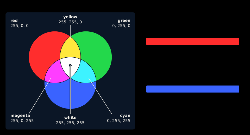
Each pixel mixes its red, green and blue LEDs. You give it three numbers, each from 0 (off) to 255 (full) [7].
| Colour | Red | Green | Blue |
|---|---|---|---|
| red | 255 | 0 | 0 |
| green | 0 | 255 | 0 |
| blue | 0 | 0 | 255 |
| magenta (red + blue) | 255 | 0 | 255 |
| white (all three) | 255 | 255 | 255 |
Adafruit’s own example makes magenta with 255, 0, 255 [7]. Try other mixes in the widget below and compare with what the ring shows later.
In the code, strip.setPixelColor(n, red, green, blue) colours pixel number n, counting from 0 [7]. The library can also pack the three numbers into one 32-bit number with strip.Color(r, g, b) [7].
Simulation and estimate, not a measurement.
Rule of thumb: 12 × 20 mA = 240 mA
Worst case (full white, full brightness): 12 × 60 mA = 720 mA
Under about 500 mA for this colour. The ring still gets its own pack.
This is the starting state: the controls need JavaScript.
How much power?
Here are the figures from Adafruit [1]:
- A pixel draws up to 60 mA at maximum brightness white (red, green and blue all full).
- In real use, with mixed colours and animations, it is much less. Adafruit uses 20 mA per pixel as a rule of thumb.
For a ring of 12:
- rule of thumb: 12 × 20 mA = 240 mA (0.24 A)
- worst case: 12 × 60 mA = 720 mA (0.72 A)
Your supply should be able to give at least the worst case if you ever light everything white. Adafruit also says extra amps are fine, because the pixels only draw what they need, but extra volts are not [1].
Why not the board’s 3V3 pin? House rule: never power a ring, or any many-LED part, from the 3V3 pin. The pixels are made for about 5 V [1]. Adafruit says even an Arduino’s 5V pin can only supply about 500 mA, and that if in doubt you should give the pixels a separate supply [4]. A ring’s worst case is 720 mA.
Keep it low. The library has strip.setBrightness(), a number from 0 to 255 that limits the brightness and the current of all the pixels. Adafruit says to call it once, in setup(), and not use it for animation [7].

Power and data: the rules
Adafruit’s best practices, for a beginner [1][2][3][4]:
- The ring gets its own supply. A holder of 3 alkaline AA cells with a switch gives about 4.5 V [1]. We choose it on purpose: at 4.5 V, the ESP32’s 3.3 V data is strong enough for the pixels (screen 5) [3]. Never four alkaline cells: they give about 6 V, too high for some NeoPixels and definitely too much for the microcontroller [1]. Lower voltages are fine, with slightly dimmer light [1].
- A big capacitor across the ring’s power. Adafruit suggests 500 to 1000 µF, rated 6.3 V or more, across the + and − [1][2]. We pick one rated 10 V or more, and 16 V gives a comfortable margin. It is an electrolytic capacitor, so it has a right way round: the stripe (and often the shorter leg) marks its − leg, which goes to GND; the other leg goes to the ring’s + [1]. Never fit it backwards. It smooths sudden changes in the current [2].
- A resistor on the data wire. Put 300 to 500 Ω between the data pin and the ring’s data input, at the end closest to the ring [2]. We use 330 Ω. It helps protect the first pixel from voltage spikes [1].
- Ground first. When connecting to a live source, connect ground (−) before anything else, and disconnect it last [1][4].
- Pixels first, board second. Power the pixels before the microcontroller. Otherwise they may try to get their power through the data wire [2]. Here: switch the pack on, then plug in USB.
- Common ground. The ring’s ground goes to both the supply’s − and a GND pin of the ESP32 [4].
- Input end only. Connect the data input, never the output [4]. Use the labels printed on your ring [4].
- Soldering. Rings often need wires soldered to their pads, and the pads are tiny: watch for solder blobs [5]. See lesson M1.
3.3 V data, 5 V pixels
Your ESP32 sends data at 3.3 V (lesson E4). The pixels are “5 V devices” [1]. Is that a problem?
Adafruit’s answer is: sometimes. The manufacturer recommends a data signal of at least 70 % of the pixels’ supply voltage [1], a figure Adafruit calls a rule of thumb [3]. At 5 V, that is 3.5 V, a little above 3.3 V. That is why our ring runs on 3 alkaline cells: about 4.5 V, and 70 % of 4.5 V is 3.15 V, below the 3.3 V of the data. Adafruit uses this exact example and says 3.3 V logic is then robust enough [3]. Brand-new alkaline cells start nearer 4.8 V (our own estimate, not Adafruit’s), where 70 % is 3.36 V, just above 3.3 V. So if the first pixel flickers or the colours are wrong, check the shared ground first, then add the 74AHCT125 level shifter (the fallback below). But the real limit varies from one make of pixel to another, and some “WS2812-compatible” parts accept less [3]. Adafruit says many projects work without any fix, but it adds that a project may work on your desk and fail somewhere else [3].
Two ways to be safe, from Adafruit [1][3]:
- Lower the pixels’ supply voltage so it is closer to the signal’s voltage.
- Add a logic level shifter between the board and the first pixel. Adafruit names chips such as the 74AHCT125 and 74HCT245 [4].
Our wiring uses the first way: the 4.5 V pack. If the colours are still wrong or flicker, check the shared ground first, then a level shifter is the next fix [3][4].
Command the ring
You need the library “Adafruit NeoPixel”. In the Arduino IDE: Sketch, Include Library, Manage Libraries, search “NeoPixel”, install “Adafruit NeoPixel by Adafruit” [6]. It supports the ESP32 [8].
The sketch draws a small “comet” that goes round the ring. Each press of the button changes its colour, and the Serial Monitor shows the three numbers.
// Tinker Mission, lesson A4: a comet of light on a 12-pixel NeoPixel ring, colours as RGB numbers
// Wiring (the ring has its OWN power: never take it from the 3V3 pin):
//   Ring data-in pad (DIN or IN) -> a 330 ohm resistor -> GPIO 23   (put the resistor close to the ring)
//   Ring power pad (5V or PWR)   -> + of a separate supply (3 alkaline AA = about 4.5 V; NEVER 4 alkaline = 6 V)
//   Ring GND pad                 -> - of that supply AND a GND pin of the ESP32 (common ground)
//   (use the labels printed on YOUR ring; connect the data-IN side, never the OUT side)
//   A capacitor of 1000 uF, 10 V or more, across the ring's 5V and GND (stripe = the - leg, to GND)
//   Button: one leg to GPIO 27, the diagonally opposite leg to GND (no resistor needed)
// Order of connection: ground first. Switch the pack ON before you plug in the USB cable.
// Each press changes the colour. The Serial Monitor shows the three numbers (red, green, blue).
// Needs the library "Adafruit NeoPixel" (Sketch > Include Library > Manage Libraries).

#include <Adafruit_NeoPixel.h>

const int DATA_PIN = 23;
const int BUTTON_PIN = 27;
const int LED_COUNT = 12;       // change this to match your ring
const uint8_t BRIGHTNESS = 40;  // limit from 0 to 255, set once in setup()
const int TAIL = 4;             // the comet is its head plus 3 dimmer pixels
const unsigned long STEP_MS = 80;

Adafruit_NeoPixel strip(LED_COUNT, DATA_PIN, NEO_GRB + NEO_KHZ800);

struct Colour {
  const char* name;
  uint8_t red;
  uint8_t green;
  uint8_t blue;
};

const Colour COLOURS[] = {
  { "red",     255,   0,   0 },
  { "green",     0, 255,   0 },
  { "blue",      0,   0, 255 },
  { "yellow",  255, 255,   0 },   // red + green
  { "magenta", 255,   0, 255 },   // red + blue
  { "cyan",      0, 255, 255 },   // green + blue
  { "white",   255, 255, 255 },   // all three: the hungriest colour
};
const int COLOUR_COUNT = sizeof(COLOURS) / sizeof(COLOURS[0]);

int colourIndex = 0;
int head = 0;
bool wasPressed = false;
unsigned long lastStep = 0;

void printColour() {
  const Colour& c = COLOURS[colourIndex];
  Serial.print(c.name);
  Serial.print(": red ");
  Serial.print(c.red);
  Serial.print(", green ");
  Serial.print(c.green);
  Serial.print(", blue ");
  Serial.println(c.blue);
}

// Draw the comet: the head in full colour, each pixel behind it half as bright as the one before.
void drawComet() {
  const Colour& c = COLOURS[colourIndex];
  strip.clear();
  for (int i = 0; i < TAIL; i++) {
    int pixel = (head - i + LED_COUNT) % LED_COUNT;
    strip.setPixelColor(pixel, c.red >> i, c.green >> i, c.blue >> i);
  }
  strip.show();
}

void setup() {
  Serial.begin(115200);
  pinMode(BUTTON_PIN, INPUT_PULLUP);
  strip.begin();
  strip.setBrightness(BRIGHTNESS);   // once, here: it limits the current for the whole sketch
  strip.show();                      // start with every pixel off
  printColour();
}

void loop() {
  bool pressed = (digitalRead(BUTTON_PIN) == LOW);
  if (pressed && !wasPressed) {      // just pressed (not held)
    colourIndex = (colourIndex + 1) % COLOUR_COUNT;
    printColour();
  }
  wasPressed = pressed;

  if (millis() - lastStep >= STEP_MS) {
    lastStep = millis();
    head = (head + 1) % LED_COUNT;
    drawComet();
  }
  delay(5);
}
Download the sketch folder (.zip)
Open the Serial Monitor at 115200 baud.
How to read it:
Adafruit_NeoPixel strip(LED_COUNT, DATA_PIN, NEO_GRB + NEO_KHZ800)creates the ring object: how many pixels, which pin, and the type of pixel.NEO_GRB + NEO_KHZ800is right for most NeoPixel products [7].strip.begin()prepares the data pin.strip.show()right after it sends “all off” [7].strip.setBrightness(BRIGHTNESS)limits the light and current once, here insetup(), as Adafruit advises [7]. At 40 out of 255, each colour is scaled to about 16 %: the white comet needs only about 20 mA, and even the whole ring in white would stay near 0.12 A instead of 0.72 A (an estimate, not a measurement) [1][7].drawComet()prepares the colours, thenshow()sends them all at once [7]. The head has the full colour. Each pixel behind it gets half of the previous one, with>> i, which halves a numberitimes.- The comet moves with
millis(), notdelay(), as in lesson K4. The button check runs all the time, so the colour changes at once. strip.clear()turns every pixel off in the prepared data [7].

Try your own changes
Change one thing, upload, observe.
- Your own colour. Add a line to
COLOURS, such as orange,{ "orange", 255, 80, 0 }. Does the ring show what you expected? Change the numbers a little at a time. - Mix by numbers. Before you upload, guess what
255, 255, 0will look like. Then check with the ring and the widget. - Brightness. Change
BRIGHTNESSto 10, then 100. Is the difference what you expected? Never go to 255 with white unless your supply can deliver the worst case [1]. - Speed and tail. Change
STEP_MSandTAIL. What happens withTAILat 1? - Two comets. Draw a second head on the opposite side of the ring,
LED_COUNT / 2further along. - Your ring size. Change
LED_COUNTto match your ring. Rings come in several sizes, such as 12, 16 or 24 pixels [5].
When it does not work
- Nothing lights up. Check that you connected the data input end, not the output [4]. Check the pack is on, and that the ring’s ground reaches both the pack and the ESP32 [4].
- Wrong colours, or blinking in a strange way. Check first that the ring, the supply and the board share a ground: the ring’s GND must go to both the supply’s − and a GND pin of the board [4]. If your pixels have a white LED too (RGBW), the declaration needs
NEO_RGBWinstead ofNEO_GRB[4][7]. - Random flicker, or wrong colours at the far end. The data signal may be too weak: try a level shifter (screen 5) [3]. Keep the data wire short [2]. A big capacitor also calms sudden changes in current [2].
- The ring or the pack gets warm. Lower
BRIGHTNESSand check your supply against the power figures [1]. - It worked, then you plugged things in a different order and it did not. Switch the pack on before USB, and connect ground first [1][2].
- “Adafruit_NeoPixel.h: No such file” when you compile. The library is not installed yet [6].
- Nothing in the Serial Monitor. Set it to 115200 baud, the same as
Serial.begin(115200).
Check yourself
Three short questions. Nothing is saved, take your time.
A ring has 12 pixels, all lit white at full brightness. What is the worst-case current, using the figure of up to 60 mA per pixel?
- 60 mA
- 240 mA
- 720 mA
You call strip.setPixelColor(3, 0, 0, 255) and nothing happens on the ring. Why?
- The colour is not sent until you call strip.show()
- Blue needs a brightness of 0
- Pixel 3 does not exist
Where should the ring get its power?
- From the board's 3V3 pin, it is the closest
- From a separate supply that suits it, with its ground joined to the board's GND
- From the data pin itself
Show the answer
From a separate supply that suits it, with its ground joined to the board's GND. A ring can ask for several hundred milliamps [1], while even an Arduino's 5V pin is said to give only about 500 mA [4]. So it gets its own supply, and the grounds are joined so that the data signal has a shared zero [4].
In short
- A NeoPixel ring is controlled with one data wire. Each pixel’s colour is three numbers from 0 to 255 for red, green and blue [4][7].
- A pixel draws up to 60 mA at full white, and much less in typical use. A 12-pixel ring is 0.24 A by the rule of thumb and 0.72 A in the worst case [1].
- Give the ring its own supply, join the grounds, add a 330 Ω resistor on the data wire and a big capacitor across the power. Never use the board’s 3V3 pin [1][2][4].
- Use
setBrightness()once insetup()to limit the current, andshow()to send the colours [7]. Powering the ring at about 4.5 V makes the 3.3 V data reliable, and a level shifter is the fix if it still is not [3].
Next step: M3, mechanisms, or build a project that needs a ring of light.
Sources
Show the 8 sources
- Adafruit, “Adafruit NeoPixel Überguide”, “Powering NeoPixels” (usually 5 V devices, lower voltages acceptable but dimmer; capacitor 500 to 1000 µF at 6.3 V or higher; 300 to 500 ohm resistor on the data line; connect ground first; up to 60 mA per pixel at maximum white, 20 mA per pixel as a rule of thumb, with the 60 mA figure for a guaranteed margin; four NiMH cells give 4.8 V, four alkaline give 6 V which is too high; extra amps are fine, extra volts are not; recommended minimum signal of 70 % of the NeoPixel voltage; two fixes for 3.3 V controllers: lower the pixel voltage or use a level shifter; three alkaline AA cells give 4.5 V) — https://learn.adafruit.com/adafruit-neopixel-uberguide/powering-neopixels
- Adafruit, “Adafruit NeoPixel Überguide”, “Best Practices” (capacitor across + and −; 300 to 500 ohm resistor at the end of the wire closest to the pixels; keep the distance short; connect ground first; power the pixels before the microcontroller or they may power themselves through the data line) — https://learn.adafruit.com/adafruit-neopixel-uberguide/best-practices
- Adafruit, “Adafruit NeoPixel Überguide”, “Logic Level Shifting” (the minimum high level is a percentage of the supply voltage, often cited as 70 %; WS2812-compatible parts may accept less; many projects work without level shifting but a bench test can pass and a field test fail; level shifting makes the signal robust; worked example: three AA alkaline cells give about 4.5 V, 70 % of that is 3.15 V, so 3.3 V logic is robust enough) — https://learn.adafruit.com/adafruit-neopixel-uberguide/logic-level
- Adafruit, “Adafruit NeoPixel Überguide”, “Basic Connections” (data from any digital pin; connect the data input, not the output; data out can feed the next chain; labels printed on the strip; level shifters such as the 74AHCT125 or 74HCT245; common ground with the supply and the board; a small board’s 5V pin supplies only about 500 mA while each pixel can draw up to 60 mA, so with many pixels give a separate supply) — https://learn.adafruit.com/adafruit-neopixel-uberguide/basic-connections
- Adafruit, “Adafruit NeoPixel Überguide”, “NeoPixel Rings” (rings with 12, 16, 24 and 60 pixels; the pads are very close together, so watch for solder blobs and short circuits) — https://learn.adafruit.com/adafruit-neopixel-uberguide/neopixel-rings
- Adafruit, “Adafruit NeoPixel Überguide”, “Arduino Library Installation” (install “Adafruit NeoPixel by Adafruit” from the Library Manager; strandtest example) — https://learn.adafruit.com/adafruit-neopixel-uberguide/arduino-library-installation
- Adafruit, “Adafruit NeoPixel Überguide”, “Arduino Library Use” (declaring the strip object with pixel count, pin and NEO_GRB + NEO_KHZ800; begin() and show(); setPixelColor(n, red, green, blue) with values 0 to 255, pixels counted from 0; Color() packs the three values; show() pushes the data and setPixelColor has no immediate effect; clear(); setBrightness() 0 to 255 to limit current and brightness, meant to be called once in setup()) — https://learn.adafruit.com/adafruit-neopixel-uberguide/arduino-library-use
- Adafruit, Adafruit_NeoPixel library, README, “Supported Chipsets” (the library lists ESP32 at any speed among its supported chipsets) — https://raw.githubusercontent.com/adafruit/Adafruit_NeoPixel/master/README.md