Lessons · Lesson S2 · Sensors · 30 min
Magnets, tilt and motion
Build a door alarm around a reed switch and a magnet, try a tilt switch, then read a PIR motion sensor and wire it safely to the ESP32. About 30 minutes, with a magnet you can drag.
The secret magnet in every door alarm
Many door and window alarms hide the same trick: a small box on the frame, a small box on the door, and nothing visible between them. One of the boxes holds a magnet. The other holds a switch that listens for it. When the door opens, the magnet moves away, and the alarm knows without touching anything.
So far, your sensors answered “beam or no beam”. This lesson adds three more ways to notice that something changed:
- a reed switch: a switch that a magnet closes,
- a tilt switch: a switch that a rolling ball closes,
- a PIR sensor: a small module that notices a warm body moving.
The first two are plain switches. You already know how to read those: lesson K2, INPUT_PULLUP. The third is a little electronic module with a mind of its own, and it needs a bit more care.

The reed switch
A reed switch has two contacts that normally do not touch: it is “normally open”, with no connection between its two wires [1]. Bring a magnet close and the two metal contacts inside pull together, so the switch closes [12]. A bare reed switch is a small glass tube and it is fragile: when you bend its legs, hold them near the body, without stressing the glass [12]. The door-alarm part sold by Adafruit is one: a reed switch inside a plastic shell, with a magnet as its partner half. Its switch closes when the magnet comes within about 13 mm (0.5 inch) [1]. Other parts have other distances, so check yours on its own page, or find out with the sketch below.
A reed switch has two wires and no polarity: it is just a switch, like the button in K2. Same recipe:
- one wire to GPIO 27,
- the other wire to
GND, INPUT_PULLUPinsetup().
Which gives:
| Door | Magnet | Switch | Pin reads |
|---|---|---|---|
| shut | next to the switch | closed | LOW |
| open | far away | open | HIGH |
The alarm therefore sounds when the pin reads HIGH, the opposite of the button in K2. There is a nice bonus: if a wire comes loose or is cut, the circuit is open, the pin reads HIGH, and the alarm sounds. A broken wire is treated like an open door. (This follows from the pull-up: with nothing connected to GND, the pin is pulled to HIGH.)
Where the picture stops. A magnet and a switch tell you the door has moved away, not who did it or how far. They only answer “closed” or “open”.
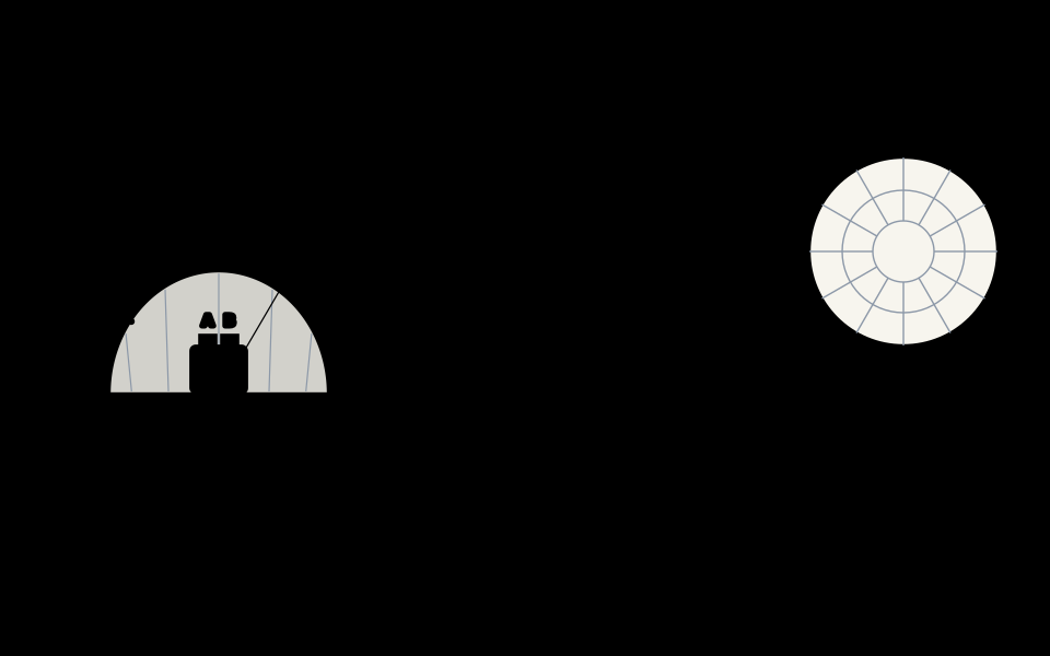
Drag the magnet in the widget on screen 5 to see a simplified reed switch close and open. (The blades in the picture are a simplified drawing, not a measurement.)

Build the door alarm
Parts: the reed switch (and its magnet), the LED on GPIO 26 through 220 Ω, and the active buzzer on GPIO 25, as in K2. Fix the switch to a frame, and the magnet on the door, a few millimetres apart when the door is shut.

Upload the sketch and open the Serial Monitor at 115200 baud:
// Tinker Mission, lesson S2: a door alarm with a reed switch (or a tilt switch)
// Wiring:
//   Reed switch (two wires, no polarity): one wire to GPIO 27, the other wire to GND (no resistor needed)
//   LED: GPIO 26 -> 220 ohm -> LED long leg; LED short leg -> GND
//   Active buzzer: + leg to GPIO 25, other leg to GND (3-pin module: VCC to 3V3, GND to GND, I/O to GPIO 25)
// Fix the switch on the door frame and the magnet on the door, a few millimetres apart when the door is shut.
// Shut door: the magnet closes the switch, the pin reads LOW. Open door: the switch opens, the pin reads HIGH.
// A tilt switch uses the same wiring. If yours closes when it tilts, set ALARM_LEVEL to LOW.

const int SWITCH_PIN = 27;
const int LED_PIN = 26;
const int BUZZER_PIN = 25;

const int ALARM_LEVEL = HIGH;   // HIGH: alarm when the switch is open. LOW: alarm when it is closed.

int lastReading = -1;           // -1 means "nothing read yet"

void setup() {
  Serial.begin(115200);
  pinMode(SWITCH_PIN, INPUT_PULLUP);   // the board's own pull-up: open switch = HIGH, closed = LOW
  pinMode(LED_PIN, OUTPUT);
  pinMode(BUZZER_PIN, OUTPUT);
}

void loop() {
  int reading = digitalRead(SWITCH_PIN);

  if (reading == ALARM_LEVEL) {
    digitalWrite(LED_PIN, HIGH);
    digitalWrite(BUZZER_PIN, HIGH);
  } else {
    digitalWrite(LED_PIN, LOW);
    digitalWrite(BUZZER_PIN, LOW);
  }

  // Print only when the reading changes, so the Serial Monitor shows real events.
  if (reading != lastReading) {
    lastReading = reading;
    if (reading == LOW) {
      Serial.println("switch CLOSED (LOW)");
    } else {
      Serial.println("switch OPEN (HIGH)");
    }
  }

  delay(20);   // a short pause between readings
}
Download the sketch folder (.zip)
With the magnet next to the switch, the LED and buzzer are off. Pull the magnet away: they come on. Bring it back: they stop. Slowly move it in and out to find your own switch’s distance.
What the new lines do:
ALARM_LEVELsays which reading means “alarm”, so you can reuse the sketch for another kind of switch by changing one line.lastReadingremembers the previous reading. The Serial Monitor prints a line only when it changes. The first reading is always printed, because-1matches nothing.delay(20)is fine here: this sketch has only one job. If you add more jobs, lesson K4 shows how to do without it.
The tilt switch
A tilt ball switch is a small metal tube with a loose metal ball inside. Tip the tube one way and the ball rolls onto the contacts and connects them. Tip it back and the ball rolls away [6]. It detects basic motion and orientation, which is why Adafruit calls it a poor man’s accelerometer [6]. It cannot say how far or how fast it moved, only that it is tipped or not.
The wiring is the same as for the reed switch, and so is the sketch. One thing to decide: which tilt closes your switch depends on how you mount it. If your alarm should sound when the switch closes, set ALARM_LEVEL to LOW and upload again.
Useful things to try:
- Mount it on a box lid, and sound the alarm when the lid is tipped.
- Watch the Serial Monitor while you tilt it slowly. The ball bounces a little inside the tube, so the connection can flicker instead of staying steady [13]. Do you see several changes in a row? Remember that when you design a project around it.
A reed switch and a tilt switch are the same family: they stay quietly in one state until something moves.

The PIR motion sensor
A PIR (passive infrared) sensor notices people and animals moving. Everything gives off some infrared radiation, and the hotter something is, the more it gives off [2]. The sensor inside a PIR is split in two halves wired so that they cancel each other out. If one half sees a bit more or less infrared than the other, the output swings [2]. So it detects change, not heat as such. A person walking across the view crosses one half and then the other [3].
A small plastic lens, made of many facets, spreads the view into several zones so that movement across them triggers the sensor [3]. The module around the sensor turns the swing into a plain digital pulse: HIGH when it sees motion, LOW when it is idle [2].
Three limits to know:
- A PIR does not tell you how many people there are or how close they are. Pets can set it off too [2].
- Detection range is typically around 6 to 7 metres, in a cone about 110 to 120 degrees wide [2][4].
- It needs time after power-up to settle: about 30 to 60 seconds [7]. That is why the sketch below begins with a countdown.
The knobs on the module. Adafruit’s PIR (product 189) has these adjustments [7]. Other modules may have similar ones, labelled differently:
- Sensitivity: a small adjustable resistor, called a trimpot. Clockwise makes it more sensitive.
- Time: another trimpot sets how long the output stays high after a detection. The range is from a few seconds to a few minutes, depending on the module (check yours). Adafruit’s guide gives roughly 2.5 s up to about 250 s for its board [7].
- Retrigger jumper (H or L). In H, the output stays high as long as motion continues. In L, the output turns on and off about once a second while you keep moving [7]. For a simple alarm, H is the easier mode [7].
Other modules sold for hobby use (the HC-SR501 is a common one) are built in the same spirit but do not have the same parts in the same places. Read what is printed on yours, or the listing where you bought it.
Try the widget below. Drag the magnet and watch the blades. Then switch to the motion tab, move the “person” across the fan, and try the sensitivity and time knobs and the retrigger jumper.
Simulation: a simplified reed switch, not a measurement.
distance: 24 mm
Your switch has its own distance: find it with the sketch.
Drag the magnet, or focus it and use the arrow keys.
Simulation: times shortened, not a real sensor.
warming up: 60 s left, output ignored
Warming up: the PIR is settling, its output is not trusted yet.
H: stays high while you move. L, simplified here: on and off about once a second.
This is the starting state: the controls need JavaScript.
Wire the PIR safely
A PIR module has three pins: power, ground and signal. The order changes from module to module, so read the labels printed next to the pins before you connect anything. Plugged in the wrong way, Adafruit’s module is not damaged but does not work [8].
Two voltages meet here, and they must not be confused:
- Power in. Adafruit says most PIR modules take 5 V to 12 V, with a small regulator inside, and that 5 V is the ideal choice [2][4]. Its connection guide gives 3 V to 5 V as the usual range, sometimes up to 12 V [8]. The two statements overlap at 5 V, so 5 V is the safe starting point. Look at your module’s own page to be sure. With the board powered through USB, use the
5Vpin of the DevKitC for the module’s supply. That is the pin Espressif names as the 5 V power supply on the header [9]. Over USB it gives a little less than 5 V, because the board has a protection diode between the USB socket and this pin [11]. A multimeter (lesson E2) typically shows around 4.6 to 4.8 V (measure yours), which most modules accept. Do not feed the board from another source at the same time: Espressif says to use one and only one of the power options, otherwise the board or the supply can be damaged [9]. - Signal out. The signal of Adafruit’s PIR is 3.3 V when high [4]. The ESP32’s input pins want high levels of at most about 0.3 V above their own supply, so 3.3 V is fine [5]. A module that puts out 5 V would not be: never connect an output you have not measured. If you are not sure, measure it with a multimeter before you connect it: black probe on
GND, red probe on the signal pin, and wave your hand so the output goes high.
One more detail: some modules have an “open collector” output, which needs a 10 kΩ pull-up resistor to give a clean level [8]. On the ESP32, connect that resistor between the signal and the 3V3 pin, never the 5V pin, so the signal can never go above 3.3 V [5]. Adafruit’s own module does not need it. If your signal never goes high, check your module’s page for this.
Connections:
- PIR power pin to the
5Vpin of the DevKitC, - PIR ground to
GND, - PIR signal to GPIO 32,
- the LED on GPIO 26 (through 220 Ω) and the buzzer on GPIO 25, as before.
The sketch:
// Tinker Mission, lesson S2: read a PIR motion sensor (module with a 3.3 V output)
// Wiring (the PIR module has three pins: check the labels printed on it):
//   PIR VCC -> the 5V pin of the DevKitC (many modules need about 5 V, see the lesson)
//   PIR GND -> GND
//   PIR OUT -> GPIO 32 (the output must be 3.3 V, never 5 V)
//   LED: GPIO 26 -> 220 ohm -> LED long leg; LED short leg -> GND
//   Active buzzer: + leg to GPIO 25, other leg to GND (3-pin module: VCC to 3V3, GND to GND, I/O to GPIO 25)
// A PIR needs time to settle after power-up: keep still and out of its view during the countdown.

const int PIR_PIN = 32;
const int LED_PIN = 26;
const int BUZZER_PIN = 25;

const int WARMUP_SECONDS = 60;   // a PIR needs about 30 to 60 seconds to stabilize

int lastReading = LOW;

void setup() {
  Serial.begin(115200);
  pinMode(PIR_PIN, INPUT);
  pinMode(LED_PIN, OUTPUT);
  pinMode(BUZZER_PIN, OUTPUT);

  Serial.println("Warming up. Keep still and stay out of the sensor's view.");
  for (int s = WARMUP_SECONDS; s > 0; s--) {
    Serial.print(s);
    Serial.println(" s left");
    delay(1000);
  }
  Serial.println("Ready.");
}

void loop() {
  int reading = digitalRead(PIR_PIN);   // HIGH = motion detected

  digitalWrite(LED_PIN, reading);
  digitalWrite(BUZZER_PIN, reading);

  if (reading != lastReading) {
    lastReading = reading;
    if (reading == HIGH) {
      Serial.println("Motion detected!");
    } else {
      Serial.println("Motion ended.");
    }
  }

  delay(50);
}
Download the sketch folder (.zip)
Wait for “Ready.”, then wave a hand across the sensor. The LED and buzzer come on while the output is high, and the Serial Monitor tells you when motion starts and ends. This is the same idea as Adafruit’s own test sketch, which also prints when the output changes [10].
What the new lines do:
for (int s = WARMUP_SECONDS; s > 0; s--)counts down from 60 to 1, one step per second. Thedelay(1000)is fine insetup(), where the board has nothing else to do.pinMode(PIR_PIN, INPUT): the module drives its output itself, so no pull-up is needed.digitalWrite(LED_PIN, reading)copies the sensor to the LED:HIGHlights it,LOWswitches it off.
Try your own changes
Change one thing, upload, observe.
- Distance test. With the door alarm, move the magnet away a millimetre at a time. At what distance does the alarm start? Note it. Is it the same on both sides of the switch?
- Opposite alarm. Set
ALARM_LEVELtoLOW. Which situation sounds the alarm now? Where could that be useful? - Knobs. Turn the PIR sensitivity trimpot a little at a time, and note the distance at which it detects your hand. Then move the retrigger jumper from H to L (if your module has one) and watch the Serial Monitor while you keep waving.
When it does not work
- Reed: the alarm is always on, or always off. Check the two wires: one must go to
GND. Then test the distance: the magnet may be too far, or on the wrong side. Check the switch’s own page for its distance (13 mm for the Adafruit one [1]). - Reed: the alarm works backwards. Swap
ALARM_LEVELbetweenHIGHandLOW, or check that the magnet sits next to the switch when the door is shut. - Tilt: several messages for one tilt. The ball bounces on the contacts [13]. Try a slower motion, or a different mounting angle.
- PIR: it fires when I power up. Normal, let the countdown finish [7].
- PIR: it never fires. Check power and pins. The labels printed on the module come first, since the pinout varies [8]. If your module needs 5 V, measure its supply pin: over USB, a little under 5 V is normal [11]. If the module has an open-collector output, a 10 kΩ pull-up to
3V3(never to5V) helps [8]. - PIR: the output stays high for a long time. The time trimpot is turned up, or the jumper is on H and something keeps moving [7].
- PIR: false alarms. Pets can trigger it [2]. Try another position, or lower the sensitivity.
- Nothing in the Serial Monitor. Set it to 115200 baud.
Check yourself
Three short questions. Nothing is saved, take your time.
A reed switch is wired between GPIO 27 and GND, with INPUT_PULLUP. The door is shut and the magnet is next to the switch. What does digitalRead() return?
- HIGH, because the switch is open
- LOW, because the magnet has closed the switch
- Nothing: a reed switch needs 5 V to work
Your PIR module is powered from 5 V, and its output measures 3.3 V when high. Can the output wire go straight to an ESP32 GPIO?
- Yes, 3.3 V is a normal high level for the ESP32's inputs
- No, the ESP32 only understands 5 V signals
- No, you always need a 10 kΩ resistor in series
Show the answer
Yes, 3.3 V is a normal high level for the ESP32's inputs. An ESP32 input accepts a high level from 0.75 times its supply up to 0.3 V above it, so 3.3 V is well inside the range [5], and Adafruit's PIR outputs 3.3 V [4]. The real danger would be a module with a 5 V output: measure an unknown module first. (A 10 kΩ pull-up is only for open-collector outputs [8].)
Right after you power up a PIR sensor, its output flickers for a while. What should you do?
- Replace it, it is broken
- Wait: it needs roughly 30 to 60 seconds to stabilize
- Turn the sensitivity all the way up
Show the answer
Wait: it needs roughly 30 to 60 seconds to stabilize. A PIR needs time to settle after power-up, and its output can flicker meanwhile [7]. The sketch counts down 60 seconds for this reason.
In short
- A reed switch is normally open and a nearby magnet closes it [1]. With
INPUT_PULLUP, shut door =LOW, open door =HIGH. A cut wire reads as an open door. - A tilt switch connects its contacts when a rolling ball reaches them [6]. Same wiring, same sketch: set
ALARM_LEVELfor the way you mount it. - A PIR senses change in infrared between its two halves, so it notices movement, not a still warm body [2]. It needs 30 to 60 seconds to settle [7].
- Power the module from
5Vif it asks for it, and make sure its signal is 3.3 V before you connect it to a GPIO [2][4][5]. - Modules differ: read the labels, then test.
Next steps: use one of these sensors as the trigger in the alarm of lesson K4. Careful: they read HIGH for “alarm”, where the K4 button read LOW, so flip that test.
Sources
Show the 13 sources
- Adafruit, “Magnetic contact switch (door sensor)”, product page 375 (essentially a reed switch in a plastic shell, with a magnet as the other half; normally open, no connection between the two wires; the switch closes when the magnet is less than 13 mm (0.5 in) away; used to detect an open door or drawer) — https://www.adafruit.com/product/375
- Adafruit, “PIR Motion Sensor”, learn guide, “Overview” (PIR sensors detect motion, usually of people; everything emits infrared and hotter things emit more; the sensor is split in two halves that cancel each other out and swing when one sees more or less IR; digital output, high (3 V) on motion and low when idle, pulse length set by parts on the board and varying between sensors; cannot tell how many people or how far away; sometimes set off by pets; range up to about 6 m (20 ft), 110° x 70°; input voltage 5 V to 12 V for most modules with a 3.3 V regulator, 5 V ideal) — https://learn.adafruit.com/pir-passive-infrared-proximity-motion-sensor/overview
- Adafruit, “PIR Motion Sensor”, learn guide, “How PIRs Work” (two slots sensitive to IR; a warm body passing intercepts one half first, then the other, producing a differential change; faceted Fresnel lens splits the view into several detection areas) — https://learn.adafruit.com/pir-passive-infrared-proximity-motion-sensor/how-pirs-work
- Adafruit, “PIR (motion) sensor”, product page 189 (adjustable delay and sensitivity; runs on 5 V to 12 V power; digital signal output is 3.3 V high or low; sensing range about 7 m, 120 degree cone) — https://www.adafruit.com/product/189
- Espressif, ESP32 Series Datasheet v5.3, section 5.3 “DC Characteristics (3.3 V, 25 °C)” (high-level input voltage between 0.75 x VDD and VDD + 0.3 V) and GPIO description (most digital GPIOs can be configured as internal pull-up or pull-down) — https://www.espressif.com/sites/default/files/documentation/esp32_datasheet_en.pdf
- Adafruit, “Tilt ball switch”, product page 173 (tilt sensors detect basic motion and orientation, a “poor man’s accelerometer”; a metal ball rolls in a metal tube and, when tilted, rolls onto the contacts at the end and shorts them together) — https://www.adafruit.com/product/173
- Adafruit, “PIR Motion Sensor”, learn guide, “Testing a PIR” (wait 30 to 60 seconds for the PIR to stabilize after power-up; retrigger jumper H keeps the output high during continuous motion, L turns the output on and off about every second; trimpot for sensitivity, clockwise more sensitive; TIME trimpot sets the output pulse length, roughly 2.5 s to 250 s on Adafruit’s board) — https://learn.adafruit.com/pir-passive-infrared-proximity-motion-sensor/testing-a-pir
- Adafruit, “PIR Motion Sensor”, learn guide, “Connecting to a PIR” (most modules have three pins and the pinout varies between modules, so check it; power is usually 3 V to 5 V DC but can be as high as 12 V; some outputs are open collector and need a 10 kΩ pull-up between signal and power; connecting the cable backwards does not damage Adafruit’s PIR but it does not work) — https://learn.adafruit.com/pir-passive-infrared-proximity-motion-sensor/connecting-to-a-pir
- Espressif, ESP32-DevKitC V4 User Guide (three mutually exclusive power options: Micro USB port, 5V and GND header pins, 3V3 and GND header pins; the supply must come from one and only one of them, otherwise the board and/or the source can be damaged; header pin “5V” described as 5 V power supply) — https://docs.espressif.com/projects/esp-dev-kits/en/latest/esp32/esp32-devkitc/user_guide.html
- Adafruit, “PIR Motion Sensor”, learn guide, “Using a PIR w/Arduino” (the PIR acts as a digital output; connect the output to a digital pin and listen for it to go high or low; example sketch prints a message when motion starts and when it ends; retrigger jumper in the H position; power the PIR with 5 V) — https://learn.adafruit.com/pir-passive-infrared-proximity-motion-sensor/using-a-pir-w-arduino
- Espressif, ESP32-DevKitC V4 schematic (USB VBUS reaches the EXT_5V net, which is the header “5V” pin, through Schottky diode D3, BAT760-7) — https://dl.espressif.com/dl/schematics/esp32_devkitc_v4_sch.pdf
- SparkFun, “Reed Switch Hookup Guide” (in a magnetic field two ferrous materials inside pull together and the connection closes; normally open; basic glass reed switches are relatively fragile, bend the legs without placing stress on the body) — https://learn.sparkfun.com/tutorials/reed-switch-hookup-guide
- Adafruit, “Tilt Sensor”, learn guide, “Using a Tilt Sensor” (the ball bounces around a little inside the can, so the connection can be a little intermittent instead of constant; example sketch with a debounce delay) — https://learn.adafruit.com/tilt-sensor/using-a-tilt-sensor